
close
Choose Your Site
Global
Social Media


Views: 0 Author: Site Editor Publish Time: 2026-08-10 Origin: Site


In commercial and industrial fire protection, underspecifying pump capacity or ignoring maintenance accessibility leads to catastrophic system failure and severe compliance penalties. Facilities requiring massive water displacement face a complex engineering challenge. When flow rates exceed 5,000 GPM, you must balance hydraulic efficiency, Net Positive Suction Head (NPSH) requirements, and long-term maintenance accessibility within the strict confines of a dedicated pump room.
Recognized as the most reliable type for heavy-duty applications, the horizontal split case fire pump is the industry standard for high-capacity needs. Standard end-suction models simply cannot handle the sheer volume and mechanical stress of these extreme environments. This guide provides a technical evaluation framework to determine if this heavy-duty pump architecture aligns with your facility's fire protection demands, spatial constraints, and compliance requirements.
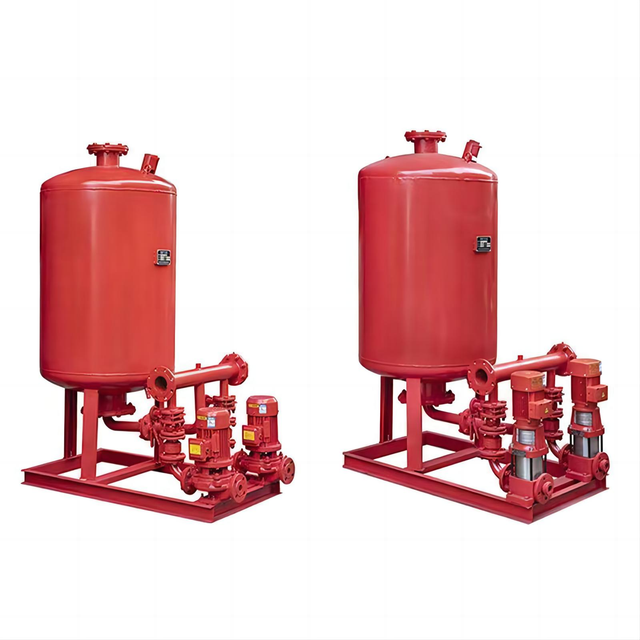
Unmatched High-Flow Capacity: Engineered as a water-moving workhorse to efficiently handle flow rates up to and exceeding 5,000 GPM, making them ideal for large-scale industrial, warehousing, and commercial applications.
Maintenance Accessibility: The split-casing design allows engineers to easily access, inspect, and repair internal components (like the impeller and bearings) without disconnecting the piping network or moving the driver.
Favorable NPSH Characteristics: Superior performance in low-suction-head environments compared to alternative pump designs, reducing the risk of cavitation.
Implementation Trade-offs: Requires a significantly larger physical footprint and strict adherence to foundation leveling and piping alignment to prevent casing strain.
Table of Contents
We establish the baseline for high-flow environments by examining the specific hazard classifications of a facility. Standard office buildings or light commercial spaces rarely push the limits of water supply. However, heavy industrial sites present extreme hazard classifications. These environments contain highly combustible materials or vast open spaces where fire spreads rapidly. Suppressing these fires requires rapid, massive water deployment.
Consider a modern distribution warehouse utilizing Early Suppression Fast Response (ESFR) sprinkler systems. These systems discharge massive volumes of water directly onto a fire to suppress it immediately, rather than just controlling its spread. A large warehouse might require a fire pump capable of delivering 2,500 to 3,000 GPM to satisfy the hydraulic demand of multiple open ESFR heads.
Aircraft hangars present an even greater challenge. NFPA 409 dictates strict requirements for foam-water deluge systems in these spaces. When a deluge system activates, it floods the entire hangar floor simultaneously. This instantaneous demand often exceeds 4,000 to 5,000 GPM. Petrochemical plants and refineries face similar demands for their cooling rings and monitor nozzles. When a facility requires thousands of gallons per minute, standard pump architectures fail. The mechanical forces inside the pump casing become too great for single-suction designs. You must select robust equipment capable of sustained, heavy-duty operation.
Net Positive Suction Head (NPSH) dictates whether a pump will operate smoothly or destroy itself through cavitation. High-flow systems are particularly vulnerable to cavitation if you specify the intake piping incorrectly. You must calculate the Net Positive Suction Head available (NPSHa) at the pump inlet. This value depends on the absolute pressure of your water source, minus the friction loss in the suction piping, minus the vapor pressure of the water.
The NPSHa must always exceed the pump's Net Positive Suction Head required (NPSHr) by a safe margin. High-flow systems draw massive volumes of water rapidly. This rapid draw creates significant friction loss in the suction pipe, which drops the pressure at the suction inlet. If NPSHa falls below NPSHr, the water vaporizes into micro-bubbles.
As these bubbles pass through the impeller into higher-pressure zones, they collapse violently. This phenomenon is cavitation. Cavitation blasts small pits into the impeller vanes, causes severe mechanical vibration, and drastically reduces the pump's ability to move water. Selecting a pump with favorable NPSH characteristics prevents this destruction. The horizontal split case fire pump naturally offers lower NPSHr due to its intake geometry, making it highly suitable for these massive flow rates.
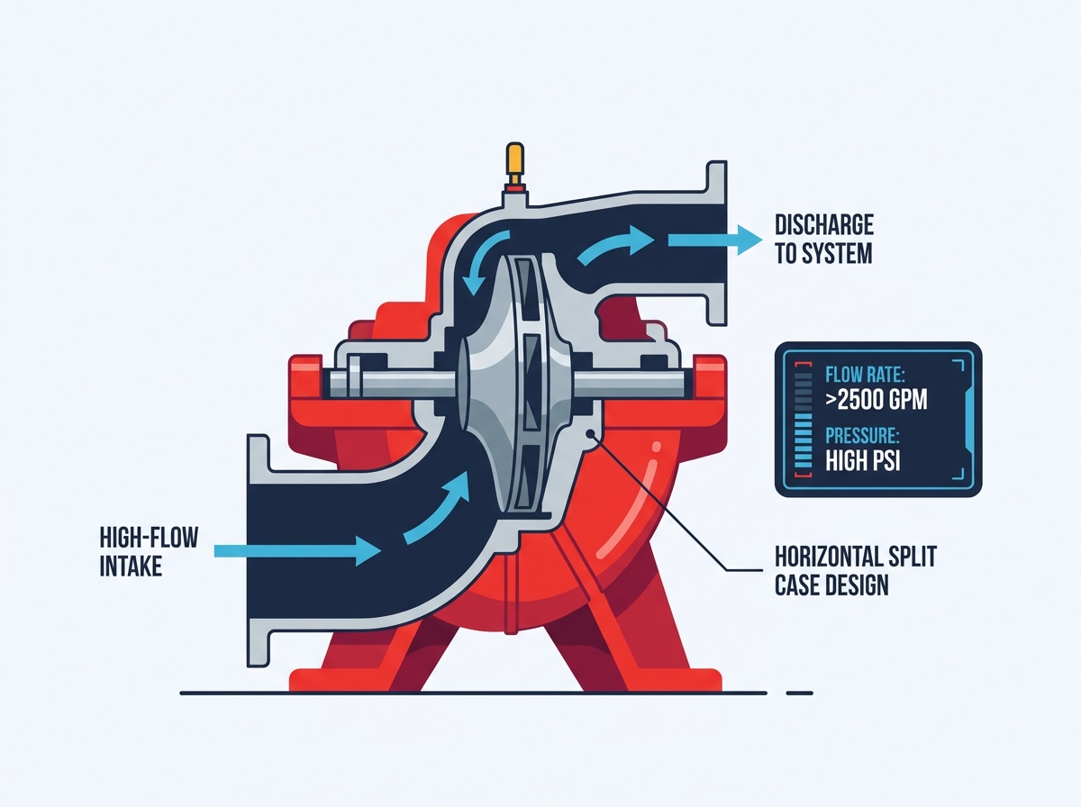
The mechanical design of this pump sets it apart from other configurations. Its unique construction provides specific advantages for maintenance, efficiency, and longevity in demanding environments.
The defining feature of this pump is its horizontal casing. The casing splits into two halves directly along the shaft centerline. The lower half connects to the suction and discharge piping and mounts securely to the baseplate. The upper half acts as a heavy-duty cover bolted securely to the lower section with a precision-cut gasket sealing the two halves.
This design drastically alters the maintenance reality for facility engineers. During a major inspection or repair, technicians simply unbolt and lift the upper half of the casing using a standard overhead hoist. This exposes the entire rotating assembly. You can remove the rotor, inspect the wear rings, and replace mechanical seals or packing without ever disturbing the suction or discharge piping.
Furthermore, you do not need to move the heavy electric motor or diesel engine. You leave the driver bolted and aligned on the baseplate. This accessibility reduces maintenance man-hours by days. End-suction models require technicians to disconnect the piping network or pull the motor back to access the impeller, which introduces massive downtime and realignment headaches. When repacking the stuffing box, technicians have clear visual access to the shaft sleeve. They can easily stagger the packing rings and adjust the gland nuts to achieve the precise leakage rate required for cooling. This level of access prevents the common error of over-tightening the packing, which scores the shaft sleeve and leads to premature failure.
Moving 5,000 gallons of water per minute requires immense energy. Hydraulic efficiency dictates the size of the driver and the electrical infrastructure required to run it. Most horizontal split case models utilize a dual-volute casing and a double-suction impeller design.
The dual-volute design splits the water flow inside the casing into two separate paths. This geometry balances the radial forces acting on the pump shaft. Unbalanced radial forces push the shaft off-center, causing premature bearing wear.
The double-suction impeller draws water from both sides simultaneously. By pulling water from opposing directions, the impeller naturally balances the hydraulic axial thrust. Single-suction pumps push all the water from one side, creating a massive thrust load that the thrust bearings must absorb. The balanced design of the split case pump leads to significantly higher efficiency, smoother operation, and greater stability at extreme flow rates.
Mechanical stability directly influences pump longevity. The split case architecture employs a between-the-bearings design. The pump shaft extends through the entire casing and is supported by heavy-duty bearings at both ends. The impeller sits squarely in the middle of the shaft.
Supporting the shaft at both ends provides a massive mechanical advantage. It drastically reduces shaft deflection when the pump operates under high pressure. Minimizing deflection prevents the shaft from whipping or vibrating inside the casing.
This stability extends the lifespan of the bearings, mechanical seals, and packing rings. Under heavy, high-pressure loads, a between-the-bearings design outlasts overhung impeller designs significantly. Overhung designs, like end-suction pumps, support the shaft on only one end, making them highly susceptible to deflection at high flow rates.
Fire protection equipment sits idle for long periods but must perform flawlessly at a moment's notice. Material integrity dictates whether the pump will survive decades of standby service and the extreme stress of emergency operation. Manufacturers typically cast the casings from heavy-duty, high-tensile cast iron or ductile iron. Ductile iron provides higher tensile strength and better resistance to thermal shock.
The impellers are usually cast from corrosion-resistant bronze or stainless steel. Bronze prevents degradation from stagnant water and resists dezincification. The shafts are machined from high-strength alloy steel or stainless steel to handle the massive torque generated by the driver.
The horizontal split case architecture is a proven industrial workhorse. You will find these exact pump designs operating continuously in demanding HVAC cooling towers, municipal water treatment plants, and pipeline booster stations. This heavy-duty pedigree translates directly to extreme reliability in fire protection scenarios.
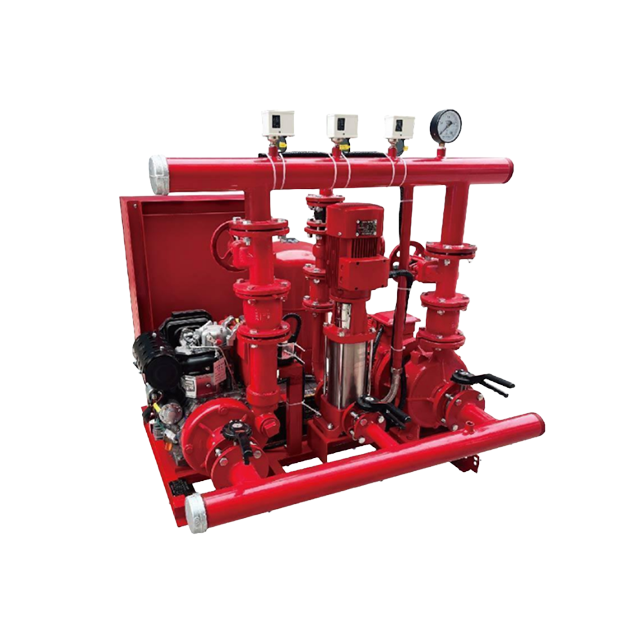
Selecting the right pump requires comparing available architectures against your facility's specific constraints. While the split case design excels in high-flow scenarios, you must evaluate the trade-offs regarding physical space and intake conditions.
Pump room real estate is often limited. Facility designers must allocate space efficiently. You must compare the spatial requirements of horizontal split case fire pumps against vertical in-line and end-suction alternatives.
Vertical in-line pumps occupy the smallest footprint. They install directly into the piping network like a large valve, saving valuable floor space. End-suction pumps require a moderate footprint but are generally limited to lower flow capacities.
The split case pump demands a significantly larger, dedicated horizontal footprint. The pump, the massive driver, and the heavy-duty baseplate require substantial floor space. You must also leave adequate clearance around the baseplate for maintenance personnel and lifting equipment. While split case pumps are vastly more efficient at higher flow rates, this spatial requirement must be factored into early facility design.
Pump Architecture | Optimal Flow Range | Footprint Requirement | Maintenance Accessibility | Axial Thrust Balance |
|---|---|---|---|---|
Horizontal Split Case | 1,500 to 5,000+ GPM | Large (Requires heavy baseplate and clearance) | Excellent (In-line repairable via top casing) | Balanced (Double-suction impeller) |
End Suction | 250 to 1,500 GPM | Moderate (Baseplate mounted) | Poor (Requires pipe or motor disconnection) | Unbalanced (Single-suction impeller) |
Vertical In-Line | 250 to 1,500 GPM | Minimal (In-line mounting, no baseplate) | Moderate (Motor removal required for access) | Unbalanced (Single-suction impeller) |
The water source dictates the intake conditions for your fire pump. You must evaluate performance differences across various scenarios, such as drawing from municipal water supplies versus dedicated ground-level tanks.
While horizontal split case pumps have lower NPSHr and are highly effective for positive suction pressure, they cannot do everything. NFPA 20 strictly dictates that horizontal split case pumps must operate under positive head. The water level in the supply tank or municipal main must be physically above the pump centerline.
They are not permitted for true suction lift applications. If your facility requires drawing water from an underground draft tank where the water level sits below the pump, you cannot use a split case pump. In those specific scenarios, vertical turbine pumps must be evaluated instead. Vertical turbines submerge the pump bowls directly into the water, eliminating the need for suction lift.
Fire protection is a heavily regulated field. Strict adherence to national standards and third-party certifications ensures the system will perform during an actual emergency.
The National Fire Protection Association outlines specific rules in the NFPA 20 standard. This document governs the installation, performance parameters, and testing of all stationary fire pumps. NFPA 20 dictates exactly how the pump must perform across its entire operational curve.
A compliant pump must deliver 150% of its rated capacity at no less than 65% of its rated head. For example, a pump rated for 2,000 GPM at 100 PSI must be capable of delivering 3,000 GPM at a minimum of 65 PSI.
Furthermore, the shutoff head (the pressure when flow is zero, or churn) cannot exceed 140% of the rated head. These strict parameters ensure the pump provides adequate pressure even when multiple sprinkler heads open simultaneously, without over-pressurizing the system when only a few heads activate. The standard also mandates specific casing relief valves to prevent the pump from overheating when operating at churn. Because the pump continues to spin and add energy to the water even when no sprinkler heads are open, the water temperature rises rapidly. The casing relief valve discharges a small amount of water to drain, providing continuous cooling flow through the casing. Engineers must verify that the selected pump curve strictly aligns with these NFPA 20 mandates.
Meeting NFPA 20 is only part of the compliance equation. You must specify only UL Listed and FM Approved pumps and components. Underwriters Laboratories (UL) and Factory Mutual (FM) are independent testing agencies. They subject fire pumps to rigorous, destructive testing protocols.
These certifications validate the manufacturer's published performance curves. They ensure the casing materials can withstand extreme pressure spikes without fracturing. They also verify that the internal components will not fail under the stress of emergency conditions.
Installing a non-certified pump in a commercial facility will result in failed inspections, voided insurance policies, and severe legal liability. The nameplate on the pump must bear the official UL and FM stamps.
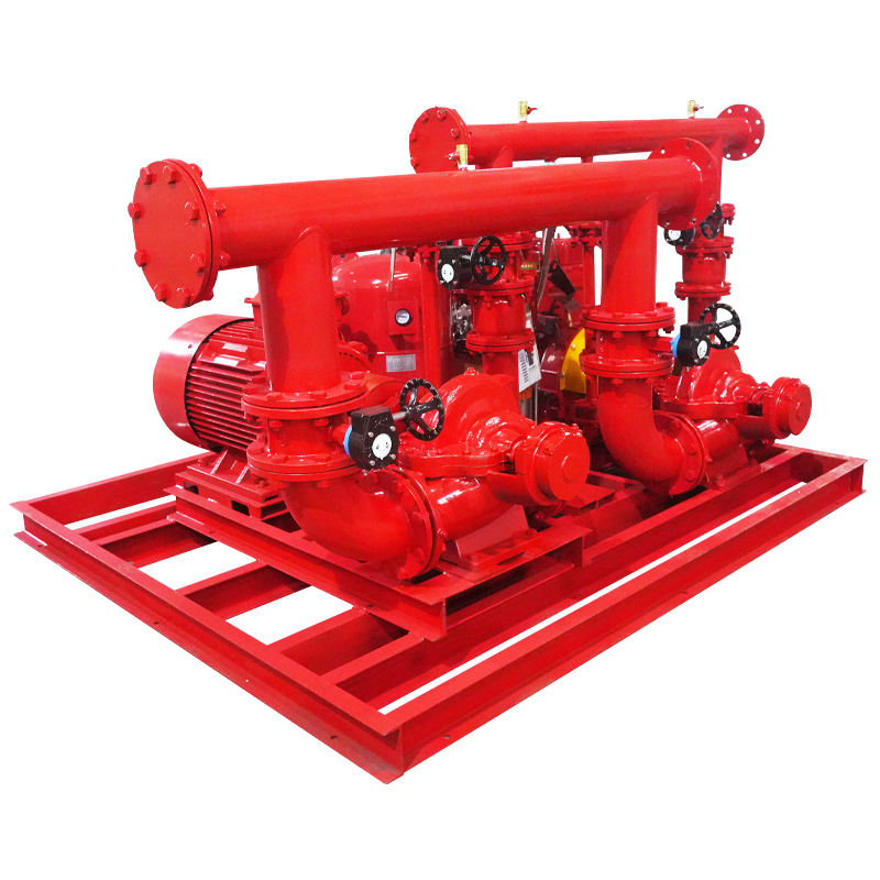
Improper installation will destroy even the most robust equipment. High-flow systems generate massive mechanical forces that must be managed through precise engineering practices.
Mounting a massive pump on a weak or uneven surface introduces severe risks. Uneven mounting surfaces cause the baseplate to twist. This twisting transfers directly to the pump casing, causing severe vibration, shaft misalignment, and premature bearing failure.
Mitigating this risk requires a massive, perfectly level concrete foundation. The foundation mass should typically be three to five times the weight of the pump and driver combined. This mass absorbs vibration and provides a rigid anchor point.
Engineers must specify proper grouting techniques. The installation process follows these steps:
Position the baseplate on the concrete foundation over the anchor bolts.
Use steel wedges or leveling nuts to achieve a perfectly level surface across the machined mounting pads.
Build wooden forms around the perimeter of the foundation.
Pour non-shrink epoxy grout under the entire baseplate, ensuring no air voids remain.
Allow the grout to cure completely before tightening the anchor bolts to their final torque specifications.
Epoxy grout provides superior chemical resistance and compressive strength compared to standard cementitious grout, locking the pump into a perfectly aligned state.
Pipes carrying thousands of gallons of water are incredibly heavy. A major installation risk occurs when improperly supported suction and discharge piping transfers weight directly onto the pump casing. Thermal expansion of the pipes also creates severe stress. This external force leads to internal misalignment, bearing failure, or catastrophic casing fracture.
You must implement strict best practices for independent pipe support. The piping network must be entirely self-supporting. You should be able to unbolt the flanges without the pipes moving a millimeter.
Use flexible connectors to isolate pump vibration from the rigid piping network. Finally, mandate strict alignment verification protocols. Technicians must use laser alignment tools to check shaft alignment both before and after the piping is attached. If the laser alignment shifts when the flange bolts are tightened, casing strain is present. The piping must be adjusted until zero strain is verified. When performing the final laser alignment, technicians must account for thermal growth. As the pump and driver reach operating temperature, the metals expand. The alignment targets must offset this growth so the shafts align perfectly during actual operation, not just when cold. Acceptable parallel misalignment is typically less than 0.002 inches, and angular misalignment must be kept below 0.0005 inches per inch of coupling diameter.
Driving a pump at 5,000+ GPM requires massive horsepower. A critical risk is undersizing the driver. You cannot size the motor just for the rated duty point. You must size the driver for the non-overloading power requirements at the very end of the pump curve. If the pump runs out past 150% capacity, an undersized motor will burn out.
Another reality is facility power grid limitations. At massive flow rates, the electrical load required by a 300 HP or 500 HP electric motor can exceed the facility's available emergency power capacity. When this occurs, you must pivot from electric motors to diesel engines.
Diesel engines provide independent, massive torque capabilities without relying on the municipal power grid. Selecting the correct driver requires mapping the maximum brake horsepower (BHP) across the entire operational curve and matching it to the driver's continuous rating. Diesel installations require additional engineering for exhaust routing, cooling loops, and fuel tank sizing. NFPA 20 requires fuel tanks to hold one gallon per horsepower, plus a 5% expansion volume.
Engage a certified fire protection engineer to perform comprehensive hydraulic calculations based on your facility's specific hazard classification and water supply data.
Verify your facility's available NPSH margins against the manufacturer's published pump curves to eliminate cavitation risks before finalizing the pump selection.
Allocate sufficient pump room space early in the architectural design phase to accommodate the larger footprint of the split case baseplate, driver, and required maintenance clearances.
Request detailed performance data, physical dimensions, and certification documents strictly from UL/FM certified manufacturers to ensure regulatory compliance.
For industrial, commercial, and municipal projects requiring reliable fluid-handling solutions, Shanghai Diequan Water Pump (Group) Co., Ltd. specializes in the design, development, manufacturing, and sales of general fluid equipment, with a product portfolio covering fire pumps, centrifugal pumps, sewage pumps, chemical pumps, and complete water supply systems. With ISO9001-based production management and experience serving applications ranging from building water supply and environmental protection to petroleum, chemical, medical, and power industries, the company can support customers in matching pump configurations to different flow, head, and system requirements.
A: These pumps are engineered for heavy commercial and industrial use. Standard ranges easily handle flow rates from 1,500 GPM up to and exceeding 5,000 GPM. Custom-engineered models can achieve even higher capacities for specialized massive-scale applications like aircraft hangars and petrochemical refineries.
A: The term refers to the pump's outer casing, which is divided into two halves horizontally along the shaft centerline. This design allows technicians to remove the top half of the casing for easy access to internal components without disconnecting the piping or moving the motor.
A: These pumps typically utilize a double-suction impeller design. By drawing water from both sides of the impeller simultaneously, the fluid velocity at the intake is reduced. This generally lowers the Net Positive Suction Head required (NPSHr), significantly reducing cavitation risks in high-flow scenarios.
A: Yes. Because the pump, the driver, and the coupling sit side-by-side on a large, shared baseplate, it requires a significantly larger horizontal footprint compared to vertical in-line pumps. Careful pump room planning is necessary to accommodate this equipment and provide adequate maintenance clearance.
A: They require a massive, perfectly level, and rigid concrete foundation. The baseplate must be properly leveled and filled with non-shrink epoxy grout. This rigid mounting prevents vibration, maintains shaft alignment, and prevents external piping strain from distorting the pump casing.
A: No. NFPA 20 rules strictly dictate that horizontal split case pumps must operate under positive suction head. The water source must be positioned above the pump centerline. For true suction lift applications, such as drawing from an underground tank, vertical turbine pumps must be used.


