
close
Choose Your Site
Global
Social Media


Views: 0 Author: Site Editor Publish Time: 2026-08-07 Origin: Site


Commercial fire sprinkler systems operate under constant pressure, but minor leaks, municipal supply fluctuations, and temperature changes continuously threaten this equilibrium, risking catastrophic system failure or severe equipment damage. When a fire protection system loses pressure, it must respond. However, triggering a massive, high-horsepower primary pump for a minor pressure drop causes violent water hammer, premature equipment wear, and costly false alarms. To prevent unnecessary wear while ensuring absolute emergency readiness, facilities rely on a dual-pump strategy. Understanding how a fire pump and jockey pump operate in tandem is critical for facility managers and engineers evaluating system upgrades and ensuring NFPA 20 compliance.
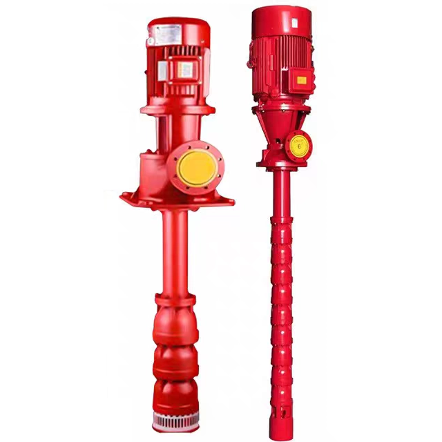
Distinct Operational Roles: The fire pump is designed exclusively for high-volume water delivery during an active fire, while the jockey pump is a low-volume maintenance tool used to stabilize everyday pressure drops and keep the system primed.
Equipment Protection & False Alarm Prevention: A properly sized jockey pump prevents the primary fire pump from "short-cycling" (starting and stopping frequently) and avoids unnecessary fire pump starts, which extends the lifespan of the primary pump and its controller.
Sequential Activation: System controllers rely on precise pressure set points to ensure the jockey pump activates first during a pressure drop, reserving the fire pump only for sustained, high-volume demand.
Compliance & Testing: Both pumps require distinct, rigorously documented testing schedules under NFPA 25 to maintain regulatory compliance and facility insurance validity.
Table of Contents
A reliable fire protection system requires immediate high-capacity suppression and long-term pressure stability without manual intervention. Achieving both outcomes requires two distinct pieces of rotating equipment. Each unit serves a highly specialized function within the hydraulic loop. You cannot substitute one for the other, nor can you operate a large-scale commercial system safely without both components working in harmony.
The primary suppression pump supplies the required water volume and pressure to sprinkler heads or standpipes. It activates when the municipal water supply proves insufficient for the building's hazard classification. These units move hundreds or thousands of gallons per minute. They overcome extreme hydraulic resistance to push water to the top floors of high-rise structures or across sprawling warehouse footprints.
Engineers specify horizontal split-case, vertical inline, or vertical turbine designs for this role. Electric motors or heavy-duty diesel engines power these massive units. Their operational reality is stark. They are designed to run continuously under heavy load until manually shut off by emergency personnel. They are not designed for frequent, short bursts of operation. Starting a 150-horsepower motor draws massive electrical inrush currents. Doing this frequently degrades motor windings, destroys contactors, and places immense mechanical stress on the pump shaft and impeller.
A complete installation includes the pump, the driver, the controller, and a suite of required accessories. These accessories include automatic air release valves for vertical turbine models, casing relief valves to prevent overheating at zero flow, and eccentric suction reducers to prevent air pockets from entering the suction flange. Every component exists to guarantee high-volume water delivery during a catastrophic event.
The secondary maintenance pump replenishes minor water loss. System leaks, thermal contraction during winter months, or minor maintenance activities cause small pressure dips. This small unit restores pressure without triggering the main suppression pump. It ensures the sprinkler pipes remain fully pressurized at all times. This guarantees zero latency in water delivery if a sprinkler head actually opens.
Manufacturers typically build these as small, multi-stage centrifugal or regenerative turbine pumps. They feature fractional or low-horsepower motors, often ranging from 0.5 HP to 5 HP. Their operational reality contrasts sharply with the primary unit. They operate automatically on a frequent basis. Engineers design them specifically for low flow and high pressure. They handle the daily rigors of system maintenance silently and efficiently, often moving just 1 to 10 gallons per minute but generating enough head pressure to overcome the static height of the building.
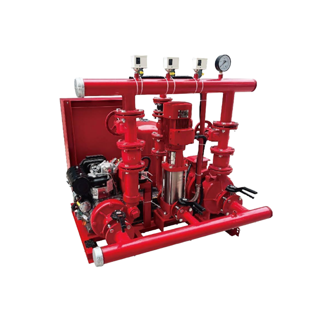
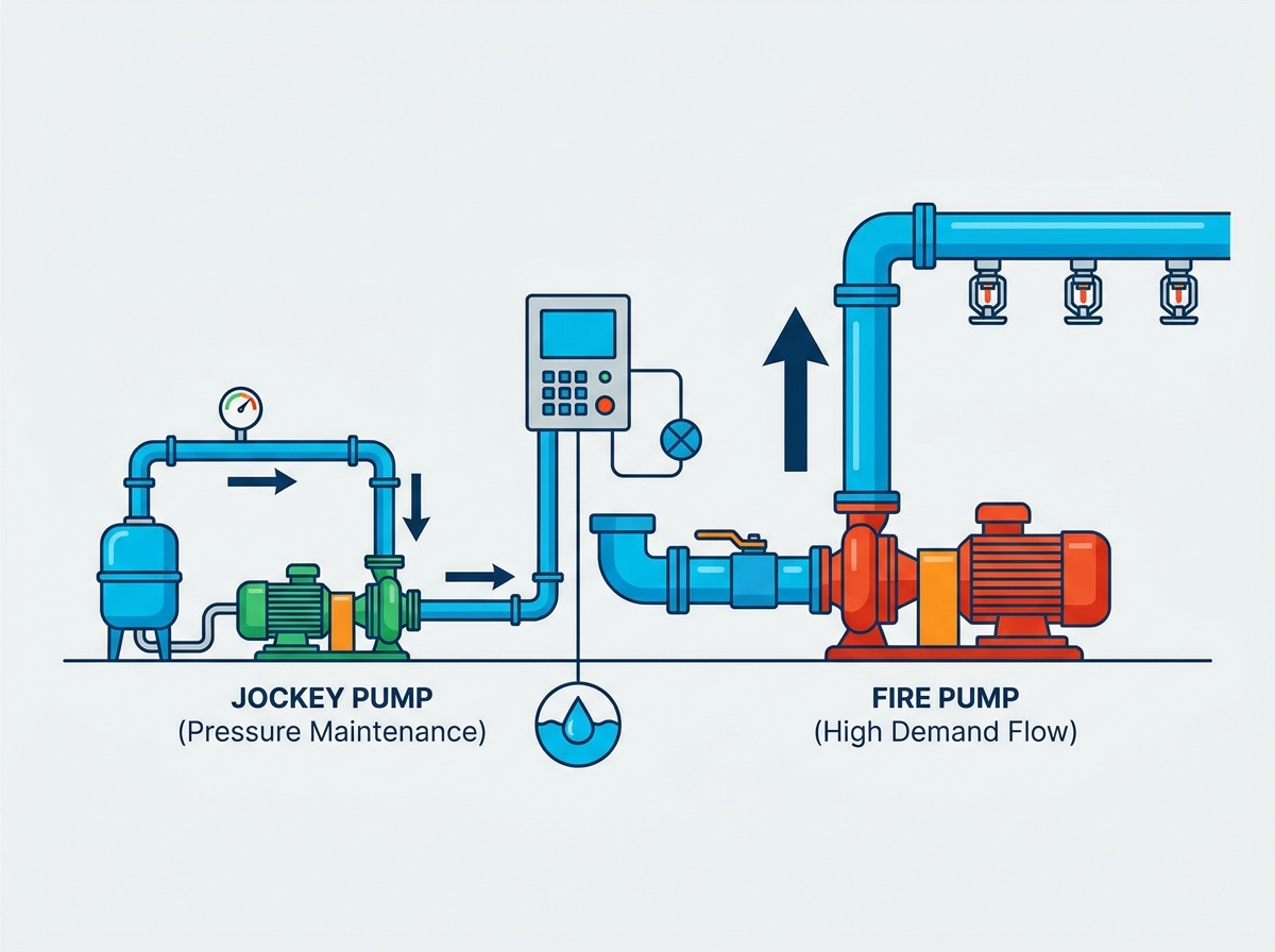
The synergy between these two units relies on automated pressure switches or solid-state transducers. Dedicated controllers monitor the system's pressure loop continuously. They translate hydraulic pressure into electrical signals to orchestrate a precise starting sequence. The sensing lines connect directly to the system piping, feeding real-time pressure data back to the controller cabinets.
During standard operations, the system remains fully pressurized. Both pumps sit in standby mode. The water inside the piping remains static. Heavy-duty check valves sit closed. They prevent pressurized water from flowing backward into the municipal supply or the dedicated storage tanks. Outside Stem and Yoke (OS&Y) valves remain locked in the open position, ensuring a clear path for water flow. The controllers monitor the static pressure, waiting for a drop.
A slow drop in pressure eventually occurs in any large system. A weeping pipe joint, thermal contraction, or a temporary dip in municipal supply pressure causes this. The pressure transducer senses this gradual decline. For example, if the normal system pressure is 120 PSI, a cold night might cause the water to contract, dropping the pressure to 110 PSI.
The secondary controller activates when pressure hits a specific threshold. Technicians usually set this activation point at 5 to 10 PSI below normal system pressure. The small maintenance pump spins up. It injects a low volume of water into the network. It runs until normal pressure is restored. Once it hits the stop set point, it automatically shuts off. This cycle successfully prevents an unnecessary and violent start of the primary suppression unit.
An actual fire alters the hydraulic dynamics instantly. A heat-sensitive glass bulb shatters, opening a sprinkler head. Alternatively, firefighters deploy a large standpipe hose. This causes a rapid, massive pressure drop across the entire system. The water escapes faster than a small maintenance pump can replace it.
The secondary maintenance pump activates first as the pressure falls past its set point. However, its low-flow design cannot keep up with the massive volume of water escaping the open sprinkler head. The pressure continues to plummet rapidly through the piping network.
The pressure then hits the primary controller's start set point. This is typically configured 5 to 10 PSI below the secondary pump's start point. The main contactor slams shut. The primary suppression pump roars to life. It delivers high-volume flow to the fire floor. Per NFPA regulations, it will continue to run continuously. Only manual deactivation by trained emergency personnel can stop it, ensuring water flows until the fire is completely extinguished.
Selecting the correct pump sizes and controller set points dictates system efficacy. Poor sizing leads to catastrophic failures. Strict adherence to NFPA 20 guidelines ensures the equipment performs exactly as designed during an emergency. Facility engineers must evaluate the hydraulic calculations carefully before approving any equipment submittals.
Engineers must size the maintenance pump meticulously. NFPA 20 dictates it must make up the allowable leakage rate within 10 minutes. Alternatively, it must provide a minimum of 1 GPM, whichever value is larger. Oversizing this unit creates severe problems. An oversized maintenance pump might mask a significant underground leak by keeping up with the flow demand, preventing the primary unit from starting when it actually should.
Pressure requirements are equally strict. The unit must achieve a pressure at least 10 PSI greater than the main pump's churn pressure. Churn pressure is the pressure generated when the pump operates at zero flow (when the pump is running but no water is leaving the system). This ensures the small pump can fully satisfy the system's pressure requirements before the main unit is ever triggered.
Engineers determine the primary unit's size through complex hydraulic calculations. They evaluate the building's hazard classification. Light hazard office buildings require vastly different flow rates than high-hazard chemical storage warehouses. The total system demand includes all active sprinklers plus the required hose stream allowances for the fire department.
The selected pump must meet specific performance points on its curve. It must deliver 100% of its rated flow at 100% of its rated pressure. Furthermore, it must deliver 150% of its rated flow at no less than 65% of its rated pressure. The churn pressure cannot exceed 140% of the rated pressure. These strict parameters guarantee the pump can handle fluctuating demands during a massive fire event.
Precise cascading pressure settings between the two controllers are mandatory. If the set points overlap, both units might start simultaneously. This causes erratic hydraulic behavior and potential power grid surges. The controllers must communicate the system status clearly through indicator lights and alarm contacts tied to the building's main fire alarm panel.
Sensing lines require careful installation. They must be entirely independent for both units. Using a single sensing line creates a single point of failure. If one line clogs with debris, both controllers become blind to system pressure. NFPA requires non-ferrous piping, typically 1/2-inch brass or copper, for these critical sensing lines. They must also include two check valves with a 3/32-inch hole drilled in the clapper to dampen pressure surges and prevent the controller from reacting to momentary water hammer.
System Parameter | Primary Suppression Pump | Secondary Maintenance Pump |
|---|---|---|
Primary Function | High-volume fire suppression | Low-volume pressure maintenance |
Flow Capacity | High (250 to 5000+ GPM) | Low (Typically 1 to 20 GPM) |
Activation Trigger | Major pressure drop (open sprinkler) | Minor pressure drop (small leak) |
Deactivation Method | Strictly manual shut-off | Automatic shut-off via pressure switch |
Motor Size | Large (20 HP to 500+ HP) | Small (Fractional to 5 HP) |
NFPA Standard | NFPA 20 (Installation), NFPA 25 (Testing) | NFPA 20 (Installation), NFPA 25 (Testing) |
Backup Power Required | Yes (Generator or Diesel Driver) | No |
Poor commissioning leads to severe mechanical damage. Incorrect settings cause false alarms and compromise building safety. Facility teams must understand these risks and implement strict mitigation protocols to keep the hydraulic loop stable.
Short-cycling occurs when the massive primary unit starts and stops repeatedly. An undersized maintenance pump causes this. A failed secondary controller or incorrectly calibrated pressure set points also trigger this phenomenon. If the maintenance pump cannot reach its shut-off pressure, the system pressure continues to drop until the main unit kicks on, pressurizes the system instantly, and then shuts down (if configured for automatic shutdown, which is rare but exists in older systems).
The impact is highly destructive. Frequent starts burn motor contacts due to repetitive inrush currents. Diesel engines suffer premature wear from cold starts. Hydraulically, short-cycling creates severe water hammer. The massive kinetic energy of starting and stopping water flow transfers to the pipe walls. This can literally tear sprinkler pipes off their hangers, rupture underground mains, and destroy alarm valves.
Mitigation requires regular calibration of all pressure switches. Technicians must verify the run-timer settings. Minimum run timers ensure that once the primary unit starts, it runs for at least 10 minutes for electric motors and 30 minutes for diesel engines. This dissipates heat from the motor windings and ensures the diesel engine reaches proper operating temperature before shutting down.
Continuous running destroys small maintenance pumps. Undetected underground leaks cause this. Municipal water supply drops also force the pump to run constantly. Sometimes, worn impellers prevent the unit from ever reaching its stop pressure set point, trapping it in an endless run cycle.
The impact is straightforward. The small motor overheats and burns out. The mechanical seals degrade rapidly due to continuous friction, eventually blowing out and flooding the pump room. Once the unit fails, the system loses its pressure maintenance capability. The next minor leak will then trigger the primary suppression unit, leading back to the short-cycling risk.
Mitigation involves implementing a "pump run" alarm on the secondary controller. This alerts facility managers if the unit runs continuously for more than 10 minutes. Regular inspections of the impeller and casing prevent performance degradation. Technicians should also perform periodic leakdown tests on the underground piping to ensure the system is tight.
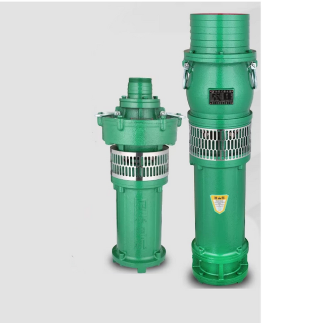
Maintaining a dual-pump system requires strict adherence to regulatory frameworks. Proper lifecycle management ensures decades of reliable service. It also optimizes energy consumption and prevents catastrophic failures during an actual emergency.
NFPA 25 mandates rigorous testing schedules. The maintenance pump requires monthly operational tests. Technicians simulate a pressure drop to verify automatic start and stop functions. They document the exact cut-in and cut-out pressures on the inspection log. They also check the packing glands or mechanical seals for excessive leakage.
The primary unit requires more intensive testing. Electric units require monthly no-flow (churn) tests. Diesel units require weekly churn tests. During a churn test, the operator starts the equipment without flowing water to the system. The casing relief valve opens slightly, discharging a small amount of water to a drain. This prevents the water inside the volute casing from boiling due to the massive friction generated by the spinning impeller. The operator checks the packing glands, ensuring they drip at a rate of approximately one drop per second to keep the shaft lubricated and cool.
Annually, the system undergoes a full-flow test. Technicians attach hoses to the test header located outside the building. They measure the exact GPM and pressure using pitot tubes and playpipes. They plot these readings on a graph and compare them to the original factory performance curve. If the pump degrades by more than 5% from its original curve, it requires immediate mechanical overhaul.
Energy consumption differs vastly between the two units. Running a 1 HP maintenance pump for pressure stabilization is highly efficient. Forcing a 150 HP primary unit to handle minor leaks wastes massive amounts of electricity and places unnecessary wear on heavy industrial components.
Facility managers must plan for routine component replacements. Pressure transducers require annual calibration. Mechanical seals on both units degrade over time and require replacement every few years. Controller contactors pit and burn after hundreds of cycles. Proactive replacement of these small components prevents the failure of the massive rotating assemblies. Keeping the pump room clean, well-lit, and heated above 40 degrees Fahrenheit prevents freezing and extends the life of all electronic controllers.
A fire pump and jockey pump are not redundant systems. They are distinct, complementary components that protect the facility and the equipment itself. The small maintenance unit acts as the sacrificial protector. It handles daily pressure fluctuations and keeps the system primed. This preserves the primary suppression unit strictly for life-safety emergencies, ensuring it operates flawlessly when lives are on the line.
When upgrading or retrofitting a fire protection system, prioritize integrated controllers. Demand precise, easily adjustable pressure transducers. Ensure engineers size the maintenance unit strictly to NFPA 20 leakage standards. Never allow contractors to oversize the secondary pump, as this masks critical system leaks.
For facilities evaluating dependable fire protection pumping equipment, Shanghai Diequan Water Pump (Group) Co., Ltd. brings more than a decade of experience in the design, development, manufacture, and supply of fluid handling equipment. Established in 2014, the company offers fire pumps, centrifugal pumps, water supply equipment, and related control solutions supported by structured quality management, customization capabilities, and technical service.
Take the following actionable steps to optimize your system:
Schedule a comprehensive hydraulic audit with a certified fire protection engineer to verify your current pressure set points.
Calibrate all pressure transducers and mechanical switches on both controllers immediately.
Install a pump-run alarm on the secondary controller to detect hidden underground leaks early.
Review your NFPA 25 testing logs to ensure both units undergo their distinct weekly and monthly operational checks.
A: Operating without a pressure maintenance unit violates most local codes and guarantees severe equipment damage. Minor system leaks cause the primary suppression unit to start frequently. This short-cycling destroys massive electric motors, burns contactors, and generates violent water hammer that can shatter pipe fittings. While the main unit technically provides the suppression water, the smaller maintenance pump protects the primary equipment from destroying itself during normal daily operations.
A: Controllers utilize cascading pressure set points to sequence activation. Technicians typically set the maintenance pump to start 5 to 10 PSI below the normal static system pressure. They configure the primary suppression pump to start 5 to 10 PSI below the maintenance pump's start point. This sequential gap ensures the smaller unit always attempts to restore system pressure before the massive primary unit activates.
A: Continuous operation indicates a hydraulic or mechanical failure. Common causes include undetected underground pipe ruptures, weeping sprinkler heads, or incorrect stop pressure settings on the controller. Drops in the municipal water supply can also force the unit to run constantly. Additionally, worn pump impellers may prevent the unit from generating enough pressure to reach its programmed shut-off threshold, requiring immediate mechanical rebuild or replacement.
A: No. NFPA 20 does not require secondary maintenance units to connect to emergency backup power. Their sole purpose is everyday pressure maintenance, not fire suppression. During a facility power outage and a simultaneous fire event, the primary suppression unit activates to handle the emergency. The primary unit always requires a reliable backup power source, such as an emergency generator or a dedicated diesel engine driver.
A: Dips in city water pressure simulate a leak within the building's internal hydraulic loop. The secondary maintenance unit absorbs these fluctuations automatically. It turns on, injects water into the system, and stabilizes the internal pressure. This action prevents the primary controller from sensing the municipal pressure drop, thereby avoiding an unnecessary and violent start of the main suppression unit.
A: NFPA 25 standards dictate testing these units at least monthly. Technicians verify the automatic start and stop capabilities by safely bleeding pressure from the sensing line via a petcock valve. They must record the exact activation and deactivation pressures on the inspection log to ensure the unit aligns with the originally commissioned set points and maintains the required cascading sequence.
A: Absolutely not. These units lack the flow capacity required to suppress a fire. They typically move between 1 and 20 gallons per minute at high pressure. Their sole purpose is pressure maintenance and system priming. Only the primary suppression unit, which moves hundreds or thousands of gallons per minute, can deliver the massive water volume needed to extinguish active flames.


