
close
Choose Your Site
Global
Social Media


Views: 0 Author: Site Editor Publish Time: 2026-08-07 Origin: Site


An improperly sized fire protection system compromises life safety and facility compliance. This is the uncompromising reality of fire protection engineering. Miscalculating hydraulic requirements introduces severe dual risks to any building project. Undersizing leads to insufficient water delivery during a fire event, causing the system to fail when suppressing the hazard. Conversely, oversizing causes pipe over-pressurization, excessive capital expenditure, and wasted mechanical room space. A rigorous, evidence-based approach to pump sizing is absolutely necessary. Engineers must carefully calculate hydraulic demand, analyze the available water supply, and apply strict NFPA 20 standards to select the correct pump performance curve. Properly integrating a fire sprinkler system pump ensures your facility meets all regulatory codes and provides reliable emergency suppression.
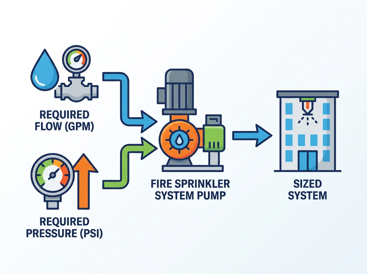
Hydraulic Demand Dictates Size: Accurate sizing requires calculating the exact flow rate (GPM) and pressure (PSI) needed at the hydraulically most remote area of the building.
The Fire Pump Performance Curve: A compliant pump must deliver 150% of its rated flow at no less than 65% of its rated pressure, per NFPA standards.
Water Supply is the Baseline: Pump sizing cannot occur in a vacuum; it requires a recent, accurate water flow test to determine the baseline static and residual pressure of the municipal supply or tank.
Compliance is Non-Negotiable: All sizing and selection criteria must strictly adhere to NFPA 20 (Standard for the Installation of Stationary Pumps for Fire Protection) and local Authority Having Jurisdiction (AHJ) requirements.
Table of Contents
A fire pump has a very specific operational purpose. It does not create water from a void. It boosts the pressure of an existing water supply to meet the hydraulic demands of the building's sprinkler system. Success is defined by delivering the exact required gallons per minute (GPM) at the necessary pressure (PSI) to the most remote sprinkler head. If the municipal water main provides 45 PSI, but the hydraulic calculations demand 85 PSI at the base of the riser, the pump must bridge that 40 PSI gap. The pump must perform flawlessly under extreme emergency conditions, and every component must align with the calculated hydraulic baseline of the facility.
You cannot use a standard domestic water pump for fire protection. Well pumps and irrigation pumps lack the required reliability and are built for entirely different duty cycles. A dedicated fire pump operates under strict regulatory standards. These units feature specialized metallurgy, such as bronze impellers and heavy-duty cast iron casings, designed to sit dormant for months and then instantly ramp up to maximum capacity. Domestic pumps prioritize energy efficiency and daily cycling, often utilizing thermal overload switches that shut the motor down if it gets too hot. Fire pumps prioritize absolute reliability and maximum output during rare emergency events. Their controllers intentionally bypass standard thermal overload protections. A fire pump will run until it destroys itself to keep water flowing onto a fire.
Not every building requires a mechanical pressure-boosting system. A pump becomes necessary only when the available water supply cannot meet the system demand. High-rise buildings frequently require pumps to overcome massive elevation losses. Pushing water up 20 stories requires immense pressure just to fight gravity. Sprawling warehouses utilizing Early Suppression Fast Response (ESFR) systems require immense water density to protect high-pile storage. This high density usually exceeds standard city water pressure capabilities. Facilities connected to weak, rural, or aging municipal water grids also require mechanical pressure assistance. Engineers determine this requirement strictly through mathematical hydraulic calculations, never by guessing.
Commercial and residential systems follow different regulatory frameworks. Commercial systems adhere to NFPA 13 standards. These require robust calculations for large-scale hazards and assume multiple simultaneous sprinkler activations. A commercial warehouse might require a pump capable of delivering 1,500 GPM. Residential systems follow NFPA 13D or NFPA 13R standards. Residential demand calculations focus on a much smaller scope, typically accounting for the activation of only one or two sprinkler heads in a living room or bedroom. The required pump size for a single-family home is exponentially smaller, often requiring only 30 to 50 GPM, and utilizes entirely different hardware configurations.
Failing to meet required pressure at the sprinkler head carries massive liability. Property risks multiply rapidly during a fire event. Insufficient pressure means the sprinkler spray pattern will not fully develop. The water droplets will be too large or the spray radius too narrow, allowing the fire to spread beyond the design area. This leads to total property loss and severe life safety hazards. Facility owners face immense legal liability if the system fails due to improper sizing. Regulatory bodies will issue heavy fines, insurance companies will deny claims, and fire marshals will revoke occupancy permits.
The facility's specific use dictates the required water density. Engineers classify buildings into Light, Ordinary, or Extra Hazard categories based on the combustibility and quantity of the materials inside. A modern office building with desks and computers represents a Light Hazard. A plastics manufacturing plant or a tire storage facility represents an Extra Hazard. Higher hazard classifications require significantly more water per square foot to suppress a fire.
Engineers use the density/area method to calculate total flow. They identify the hydraulically most demanding design area in the building, which is usually the area furthest from the water source. They multiply the required density by the square footage of this design area. For example, an Ordinary Hazard Group 2 facility requires a density of 0.20 GPM per square foot over a 1,500 square foot design area. Multiplying these figures yields a baseline requirement of 300 GPM for the sprinklers alone.
You must also include hose stream allowances in your calculations. Firefighters connect hoses to the system or nearby hydrants during an emergency. This draws water away from the sprinklers. NFPA standards require adding a specific GPM allowance for inside and outside hose streams. For the Ordinary Hazard example above, NFPA 13 requires a 250 GPM hose stream allowance. You add this allowance to the 300 GPM sprinkler demand to find the final required flow rate of 550 GPM.
Elevation loss heavily impacts pump sizing. You must overcome gravity to push water to the top floor of a structure. Physics dictates a pressure loss of 0.433 PSI for every foot of elevation gain. A sprinkler head located 100 feet above the pump requires an additional 43.3 PSI just to lift the water to that height. Building height is a primary variable in pressure calculations, and engineers must measure the exact vertical distance from the pump discharge flange to the highest sprinkler deflector.
Friction loss is another major variable. Water loses energy as it travels through the piping network. Valves, backflow preventers, elbows, and tees create physical resistance. Engineers calculate this resistance using the Hazen-Williams formula. This formula accounts for pipe length, internal diameter, and the roughness coefficient (C-value) of the pipe material. Wet steel pipe typically uses a C-value of 120, while smoother CPVC pipe uses a C-value of 150. You must calculate the cumulative friction loss through every single fitting from the pump to the most remote sprinkler head.
The system must maintain a minimum operating pressure at the most hydraulically remote sprinkler head. This is typically between 7 and 15 PSI for standard spray sprinklers, but can exceed 50 PSI for specialized ESFR heads. The exact requirement depends on the specific sprinkler head type and its K-factor (discharge coefficient). You add this minimum end-head pressure to the elevation loss and the total friction loss to determine the total system pressure demand.
Hazard Classification | Typical Occupancy Examples | Standard Density Requirement (GPM/sq. ft.) | Hose Stream Allowance (GPM) |
|---|---|---|---|
Light Hazard | Offices, Schools, Hospitals, Churches | 0.10 | 100 |
Ordinary Hazard (Group 1) | Restaurant Seating, Auto Parking, Bakeries | 0.15 | 250 |
Ordinary Hazard (Group 2) | Retail Stores, Machine Shops, Libraries | 0.20 | 250 |
Extra Hazard (Group 1) | Plywood Manufacturing, Printing, Saw Mills | 0.30 | 500 |
Extra Hazard (Group 2) | Flammable Liquid Spraying, Plastics Processing | 0.40 | 500 |
Pump sizing cannot happen without knowing the exact capabilities of the existing water supply. You must conduct a recent hydrant flow test at the specific project location. Relying on outdated flow test data or generic city averages is a dangerous engineering practice. Municipal water supplies fluctuate constantly due to new residential developments, aging infrastructure, and pipe scaling. A certified technician must perform the test using calibrated pressure gauges and pitot tubes. They open a flow hydrant to measure the discharge velocity while simultaneously reading the pressure drop on an adjacent test hydrant.
The flow test measures two distinct pressure values that dictate pump selection. Static pressure is the baseline pressure in the water main under non-flowing conditions. It represents the potential energy of the system when no water is moving. Residual pressure is the pressure remaining in the main while water is actively flowing from the test hydrant. Residual pressure is the critical metric for fire protection. It tells you how the municipal supply behaves under heavy demand. Your pump must compensate for the drop between static and residual pressure to ensure adequate supply during a fire.
Municipal water grids degrade over time. Pipe corrosion, mineral buildup, and increased neighborhood demand reduce available flow year after year. Engineering best practices require factoring in a safety margin. You typically apply a 10% to 20% degradation allowance to the flow test results. If your test shows 60 PSI of residual pressure, you design the system assuming only 48 to 54 PSI will be available. This ensures the pump will still meet system demands ten or twenty years in the future. Failing to include this allowance often results in a non-compliant system that fails its annual flow tests down the road.
Many facilities do not rely on pressurized city mains. They draft water from static suction sources. These include ground-level corrugated steel storage tanks, concrete break tanks, or underground reservoirs. Sizing considerations change drastically with static tanks. The pump does not receive any incoming pressure assistance from a municipal grid. It must generate 100% of the required system pressure on its own. You must also account for the specific volume of the tank to ensure it meets the required duration of flow. If the system demands 1,000 GPM for a 60-minute duration, the tank must hold a minimum of 60,000 usable gallons, plus additional capacity for the pump's minimum submergence levels.
NFPA 20 establishes strict performance benchmarks for all approved pumps. A compliant unit must be capable of providing 150% of its rated flow capacity. At this massive peak flow, it must maintain a pressure no less than 65% of its rated pressure. If you select a pump rated for 1,000 GPM at 100 PSI, it must physically be able to pump 1,500 GPM while maintaining at least 65 PSI. This rule ensures a robust safety margin during severe, multi-head fire events or when firefighters connect multiple hoses. The pump must not stall, cavitate, or suffer a catastrophic pressure drop when demand spikes.
You must cross-reference your calculated system requirements with official manufacturer datasheets. Never rely on generic estimates for life safety equipment. Manufacturer cut sheets provide the exact performance metrics for specific pump models, casing sizes, and impeller trims. You must verify that the selected hardware meets the NFPA 20 criteria under your specific site conditions, accounting for the exact RPM of the motor or engine driving the unit.
Engineers map the calculated system demand point against the manufacturer's pump curve on N^1.85 hydraulic graph paper. The system demand point represents your required GPM and PSI. This point must fall on or below the pump's performance curve. Proper mapping ensures the pump operates efficiently within its designated range. It guarantees the hardware can physically deliver the required hydraulic output without pushing the motor into its service factor limits.
Churn pressure is the maximum pressure the pump generates at zero flow. This occurs when the pump is running, but no sprinkler heads are open and no water is flowing out of the system. The water simply churns inside the pump casing, generating heat and maximum pressure. NFPA rules dictate that churn pressure must not exceed 140% of the pump's rated pressure. Understanding churn pressure is vital for protecting the integrity of the piping network and selecting the correct pressure ratings for underground lead-in pipes.
Exceeding the pressure ratings of system components is highly dangerous. Standard fire sprinkler fittings, grooved couplings, and butterfly valves are typically rated for 175 PSI. If the pump's churn pressure combined with the static supply pressure from the city main exceeds 175 PSI, the pipes may rupture before a fire even starts. You must implement risk mitigation strategies. This often involves installing pressure relief valves, utilizing variable speed electric drivers, or upgrading the entire piping network to heavy-wall pipe and 300 PSI-rated system components.
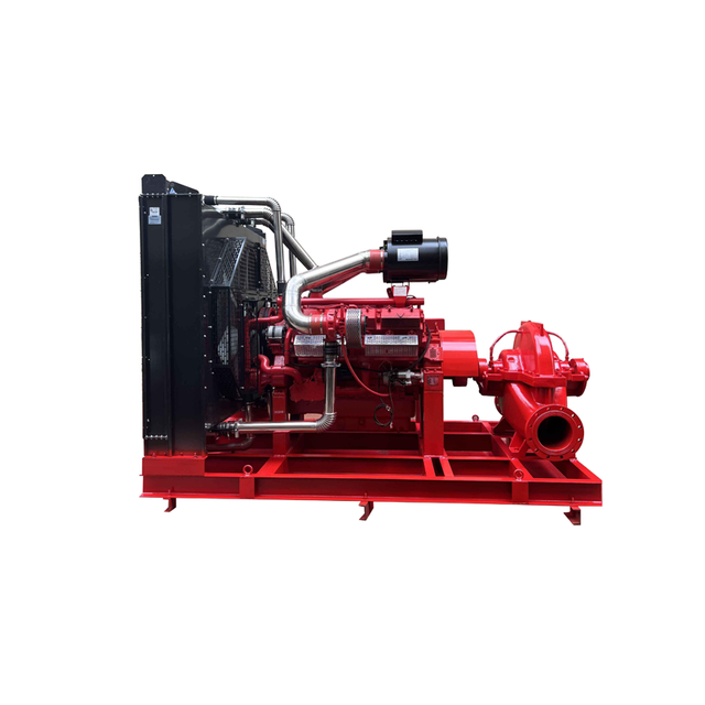
The horizontal split-case pump is a traditional, highly reliable option found in many large facilities. It features a casing split along the horizontal axis, allowing mechanics to remove the top half for easy access to the impeller and bearings without disturbing the suction or discharge piping. These pumps handle massive flow rates efficiently, often exceeding 5,000 GPM. However, they require significant mechanical room space for the pump, the driver, and the large suction headers. They are ideal for large industrial facilities where space is not a primary constraint.
Vertical in-line pumps offer excellent space-saving benefits. The motor sits directly above the pump casing, and the unit mounts directly into the piping network like a large valve. This vertical orientation drastically reduces the required floor footprint. They are highly popular for commercial retrofits, high-rise office buildings, and tight mechanical rooms. While they save space, maintenance can be more difficult because mechanics must physically lift and remove the heavy electric motor to access the pump internals.
Vertical turbine pumps are highly specialized units. They are the only NFPA-approved pump type for negative draft situations. You use them when lifting water from below-grade tanks, underground reservoirs, or natural water sources like ponds and rivers. The pump bowls sit submerged in the water, pushing it up through a vertical column pipe to the discharge head on the surface. They eliminate the need for priming, ensuring immediate water delivery during an emergency, but require deep wet pits and careful alignment during installation.
Pump Type | Best Application | Primary Advantage | Primary Disadvantage |
|---|---|---|---|
Horizontal Split-Case | Large industrial, high flow demand | Easy maintenance access to internals | Requires a massive floor footprint |
Vertical In-Line | Commercial retrofits, tight spaces | Extremely compact design | Motor must be removed for repairs |
Vertical Turbine | Underground tanks, open bodies of water | Handles negative suction lift | Complex installation and alignment |
End Suction | Small to medium commercial buildings | Cost-effective for lower flows | Limited to lower GPM capacities |
Electric motors are the most common power source for modern fire protection systems. They require lower maintenance, operate much quieter than diesel engines, and do not produce exhaust fumes. They also have a smaller physical footprint and do not require on-site fuel storage. However, electric pumps rely entirely on the facility's power grid. If the grid fails during a fire, the pump fails. They often require a highly reliable secondary power source, a dedicated backup generator, or an automatic transfer switch wired ahead of the building's main disconnect.
Diesel engines provide complete independence from the electrical grid. They run reliably even during total facility power loss, making them ideal for rural areas, earthquake zones, or facilities with unstable power infrastructure. The downsides are significant. Diesel pumps require large double-wall fuel storage tanks sized for 1 gallon per horsepower plus a 5% expansion volume. They require complex exhaust routing through the building roof, cooling water loops, and strict battery maintenance. They also require weekly test runs for a minimum of 30 minutes to ensure the engine remains in working condition.
A pressure maintenance pump, commonly called a jockey pump, is essential for system longevity. It prevents the main pump from short-cycling due to minor pressure leaks. Small fluctuations occur naturally in any large piping network due to temperature changes, trapped air, or tiny leaks at threaded joints. The jockey pump activates automatically to restore this lost pressure. It prevents the massive main motor from turning on unnecessarily, which would cause severe wear and tear on the contactors and bearings.
You must size the jockey pump correctly. Engineers typically size it for 1% of the main pump's rated flow, or at least enough to overcome the allowable leakage rate of the underground piping. The pressure setting should be approximately 10 PSI higher than the main pump's churn pressure. This precise configuration ensures the jockey pump handles all minor pressure drops. The main pump remains dormant until a genuine high-flow emergency occurs, such as a sprinkler head shattering.
The pump controller is the brain of the system. You must match the controller to the specific pump and the facility's power supply. Mismatched controllers cause severe electrical inrush issues. When a massive electric motor starts across-the-line, it draws a massive current spike, often 600% of its full load amps. Wye-Delta closed transition, soft start, or variable speed controllers mitigate this spike. They protect the building's electrical infrastructure from severe voltage drops, blown fuses, and tripped breakers during startup.
Installation is only the first step. NFPA 20 requires a certified field acceptance test before the system goes live. This test verifies that the installed pump matches the theoretical performance curve. Technicians flow water through specialized test headers or closed-loop flow meters. They measure the exact GPM and PSI at churn (0% flow), 100% rated flow, and 150% rated flow. They also measure voltage and amperage across all phases of the electric motor. This physical verification ensures the system will perform exactly as engineered during a real fire.
Hire a licensed Fire Protection Engineer (FPE) to perform certified hydraulic calculations based on current site conditions and hazard classifications.
Schedule a certified hydrant flow test to establish an accurate baseline for your municipal water supply before selecting any equipment.
Specify the exact pump requirements, including impeller trim and controller type, to ensure compatibility with your mechanical room space and electrical infrastructure.
Verify that all selected system components, including valves and fittings, are rated to withstand the maximum churn pressure generated by the new pump.
Schedule a comprehensive NFPA 20 field acceptance test with the local Authority Having Jurisdiction (AHJ) to commission the system prior to building occupancy.
For projects requiring dependable fire protection and fluid-handling solutions, Shanghai Diequan Water Pump (Group) Co., Ltd. specializes in the design, development, manufacturing, and supply of fluid equipment, with a product portfolio that includes fire pumps, centrifugal pumps, sewage pumps, chemical pumps, and complete water supply systems. With an established quality management system, technical capabilities, and installation and after-sales support, the company provides pump solutions for a wide range of commercial, industrial, and infrastructure applications.
A: The 150% rule is a strict NFPA 20 performance requirement. It mandates that a fire pump must be capable of delivering 150% of its rated flow capacity. While operating at this peak demand, the pump must maintain no less than 65% of its rated pressure. This ensures a safety margin during severe fires.
A: The required pressure varies by building design. You must calculate the minimum operating pressure of the most remote sprinkler head. You then add the pressure lost to elevation, calculated at 0.433 PSI per foot of height, and the friction loss through all pipes and fittings using the Hazen-Williams formula.
A: No. Pumps are only required when the existing municipal water supply or static tank cannot meet the system's calculated hydraulic demand. If the city water pressure is high enough to overcome elevation and friction losses while delivering the required flow, a pump is unnecessary.
A: You calculate GPM using the density/area method. First, determine the building's hazard classification to find the required water density. Multiply this density by the square footage of the most demanding design area. Finally, add the required NFPA hose stream allowance to get the total GPM.
A: A fire pump provides massive, emergency high-volume flow during a fire. A jockey pump is a small pressure maintenance unit. It runs intermittently to maintain baseline pipe pressure against minor leaks or temperature changes, preventing the large main pump from turning on unnecessarily.
A: Oversizing creates severe risks. It can generate excessive churn pressure that exceeds the 175 PSI rating of standard system components, leading to pipe ruptures and water hammer. It also wastes mechanical room space, requires larger electrical infrastructure, and unnecessarily increases capital and maintenance expenditures.
A: Yes, but it requires a specific pump type. Standard horizontal pumps cannot pull water up from a negative draft. You must use a vertical turbine pump. The pump bowls are submerged directly in the underground tank, pushing the water up the column without needing to be primed.


